New
Never sold or installed
Regularly $1449
End of season blow out
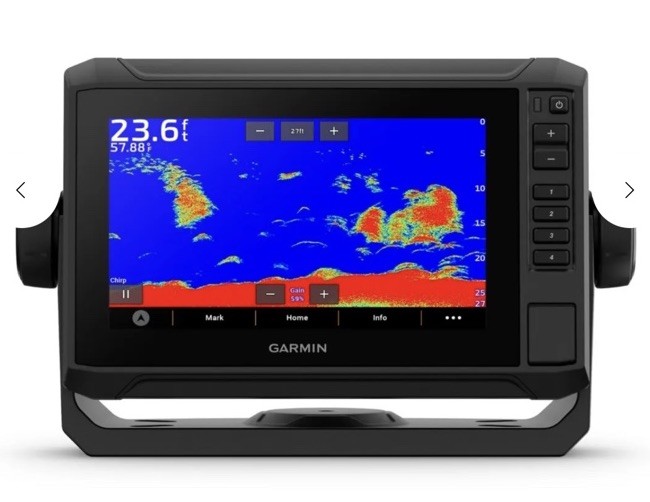
* Display & Maps
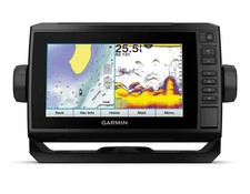
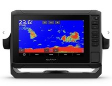
* Bright, sunlight-readable 7” (17.8 cm) touchscreen.
* Share data and maps with select ECHOMAP devices on your network.
* Connectivity & Data
* Use built-in Wi-Fi® to pair with the free ActiveCaptain™ app for access to OneChart™, smart notifications¹, Garmin Quickdraw™ Community data and more.
* Installation & Compatibility
* Features a quick-release bail mount for quick installation and removal.
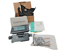
* Included
* GPS support included for installation.
* Transducer not included, provides GPS function only.
* Preloaded worldwide basemaps and compatible with Bluechart ® G3 coastal charts (sold separately).
Powered by
Translate
Installation instructions
PWC KIT - Garmin ECHOMAP™ UHD 72sv - GPS Kit and Support - GTI, GTR and Wake 170
Product: Sea-Doo_watercraft
Project no: 487803714_rev1
Instruction Sheet P/N: 487803714
Revision no: 1
Revision date: September, 2025
Item covered: Garmin ECHOMAP™ UHD 72sv - GPS Kit and Support - GTI, GTR and Wake 170
The following symbols may be used in this document:
WARNING
Indicates a hazardous situation which, if not avoided, could result in death or serious injury.
CAUTION: Indicates a hazard situation which, if not avoided, could result in minor or moderate injury.
NOTICE Indicates an instruction which, if not followed, could severely damage vehicle components or other property.
WARNING
- For safety reasons, this kit must be installed by an authorized BRP dealer.
- This kit is designed for specific applicable models only (authorized BRP dealers will confirm model(s)). It is not recommended for units other than the one (those) for which it was sold.
- Should removal of a locking device (e.g. lock tabs, self-locking fasteners, etc.) be required when undergoing disassembly/ assembly, always replace with a new one.
- Torque wrench tightening specifications must strictly be adhered to.
- Unless otherwise specified, engine must be OFF when performing any operation on the vehicle.
- Always wear EYE PROTECTION AND APPROPRIATE GLOVES when using power tools.
- Some components may be HOT. Always wait for engine to cool down before performing work.
WARNING
Some important safety information and/or operating instructions dedicated to the end user might be included in this instruction sheet. Make sure to give the kit part number as well as the instruction sheet included with this kit to the customer. Verify that the customer has access to all the information required for proper use of the accessory.
NOTE: USE TIGHTENING TORQUES IN THE FOLLOWING TABLE IF NOT OTHERWISE SPECIFIED.
GRADE
5.8 8.8 10.9 12.9
M4 1.8 ± 0.2 N•m (16 ± 2 lbf•in) 2.8 ± 0.2 N•m (25 ± 2 lbf•in) 3.8 ± 0.2 N•m (34 ± 2 lbf•in) 4.5 ± 0.5 N•m (40 ± 4 lbf•in)
M5 3.3 ± 0.2 N•m (29 ± 2 lbf•in) 5 ± 0.5 N•m (44 ± 4 lbf•in) 7.8 ± 0.7 N•m (69 ± 6 lbf•in) 9 ± 1 N•m (80 ± 9 lbf•in)
M6 7.5 ± 1 N•m (66 ± 9 lbf•in) 10 ± 2 N•m (89 ± 18 lbf•in) 12.8 ± 2.2 N•m (113 ± 19 lbf•in) 16 ± 2 N•m (142 ± 18 lbf•in)
M8 15.3 ± 1.7 N•m (135 ± 15 lbf•in) 24.5 ± 3.5 N•m (18 ± 3 lbf•ft) 31.5 ± 3.5 N•m (23 ± 3 lbf•ft) 40 ± 5 N•m (30 ± 4 lbf•ft)
M10 29 ± 3 N•m (21 ± 2 lbf•ft) 48 ± 6 N•m (35 ± 4 lbf•ft) 61 ± 9 N•m (45 ± 7 lbf•ft) 73 ± 7 N•m (54 ± 5 lbf•ft)
M12 52 ± 6 N•m (38 ± 4 lbf•ft) 85 ± 10 N•m (63 ± 7 lbf•ft) 105 ± 15 N•m (77 ± 11 lbf•ft) 128 ± 17 N•m (94 ± 13 lbf•ft)
M14 85 ± 10 N•m (63 ± 7 lbf•ft) 135 ± 15 N•m (100 ± 11 lbf•ft) 170 ± 20 N•m (125 ± 15 lbf•ft) 200 ± 25 N•m (148 ± 18 lbf•ft)
M16 126 ± 14 N•m (93 ± 10 lbf•ft) 205 ± 25 N•m (151 ± 18 lbf•ft) 255 ± 30 N•m (188 ± 22 lbf•ft) 305 ± 35 N•m (225 ± 26 lbf•ft)
M18 170 ± 20 N•m (125 ± 15 lbf•ft) 273 ± 32 N•m (201 ± 24 lbf•ft) 330 ± 25 N•m (243 ± 18 lbf•ft) 413 ± 47 N•m (305 ± 35 lbf•ft)
The illustrations in this document show typical construction of the different assemblies and may not reproduce the full detail or exact shape of the parts; however, they represent parts that have the same or similar function.
Installation time is approximately 1.0 hour.
PARTS TO BE INSTALLED
ITEM DESCRIPTION PART NUMBER QTY
P1 ECHOMAP Plus UHD 72sv ass'y 278003929 1
P2 Support 269502461 1
P3 Mirror cover RH 269502375 1
P4 Power supply harness 278003974 1
P5 M6x35 Hex cap Screw 250000399 2
P6 10-14 x 7/8 Hex Plastite Screw 211000023 2
P7 Locking tie 188mm 414115200 4
P8 Clip 515178223 1
NOTE: If your vehicle is equipped with a sound system, MULTIPLE ACC HARNESS (P/N 278003684) is Preparation
Refer to SERVICE MANUAL to remove the following components:
- Top cover, hood cover and RH mirror cover
- Seats
- Lateral trim panels
- Mirror support
Installation Instructions
1. Route power supply harness [P4] and attach it to steering harness with locking ties [P7] as shown.
NOTE: If your vehicle is equipped with an accessory connected to the front ACC connector (except the USB port), use MULTIPLE ACC HARNESS (P/N 278003684) to split the power.
Plug harness into connectors and secure fuse with locking tie [P7]. Install the connectors as shown using the clip [P8].
1. Power supply harness [P4]
2. Fuse
3. Clip [P8]
4. Locking tie [P7]
Use a 22 mm (7/8 in) diameter unibit drill or a small rotary tool to enlarge existing hole in the mirror support to allow routing of the connector.
NOTICE Carefully perform drilling to avoid any visible damage on the mirror support.
Do not drill too deep to avoid damage on the surface below.
NOTE: Position the tool to be tangent with the mirror support wall and the opening as shown.
Drill at an angle to prevent damaging the aesthetic side.
2. Install support [P2] on mirror support and secure it with two M6x35 Hex cap screws [P5]. Tighten to specification.
1. Support [P2]
2. M6x35 Hex cap screw [P5]
3. Route power supply harness [P4] through mirror support and support [P2] as shown. Secure support [P2] with a 10-14 x 7/8 hex Plastite screws [P6]. Tighten to specification.
1. M6x35 Hex cap screw [P5]
2. 10-14 x 7/8 Hex Plastite screws [P6]
4. Reinstall mirror support on vehicle.
5. Install mirror cover RH [P3] using 10-14 x 7/8 Hex Plastite screw [P6]. Tighten to specification.
1. Mirror cover RH [P3]
2. 10-14 x 7/8 Hex Plastite screws [P6]
Tightening torque
M6x35 Hex cap screw [P5] 5.5 ± 0.5 N•m (49 ± 4 lbf•in)
10-14 x 7/8 Hex Plastite Screw [P6] 3.5 ± 0.5 N•m (31 ± 4 lbf•in)
6. Plug the harness into the screen. Install ECHOMAP Plus UHD 72sv assy [P1] on support [P2].
NOTE: Be careful while plugging the harness to the monitor, the connector has a specific indexation.